LTD Power by Bagel

Discussion on Stirling or "hot air" engines (all types)
Jerry
Posts: 79
Joined: Sun Jul 29, 2012 10:42 pm
Location: Las Vegas

Re: LTD Power by Bagel

Post by Jerry »

Anyone know what alloy Hasbro Easy Bake Oven pans are made from? They appear to be anodized alluminum, but there is no tech specs at Hasbor's site, and Google has failed me. I've found some third party sellers of accesories for the oven, and they state anodized alluminum.

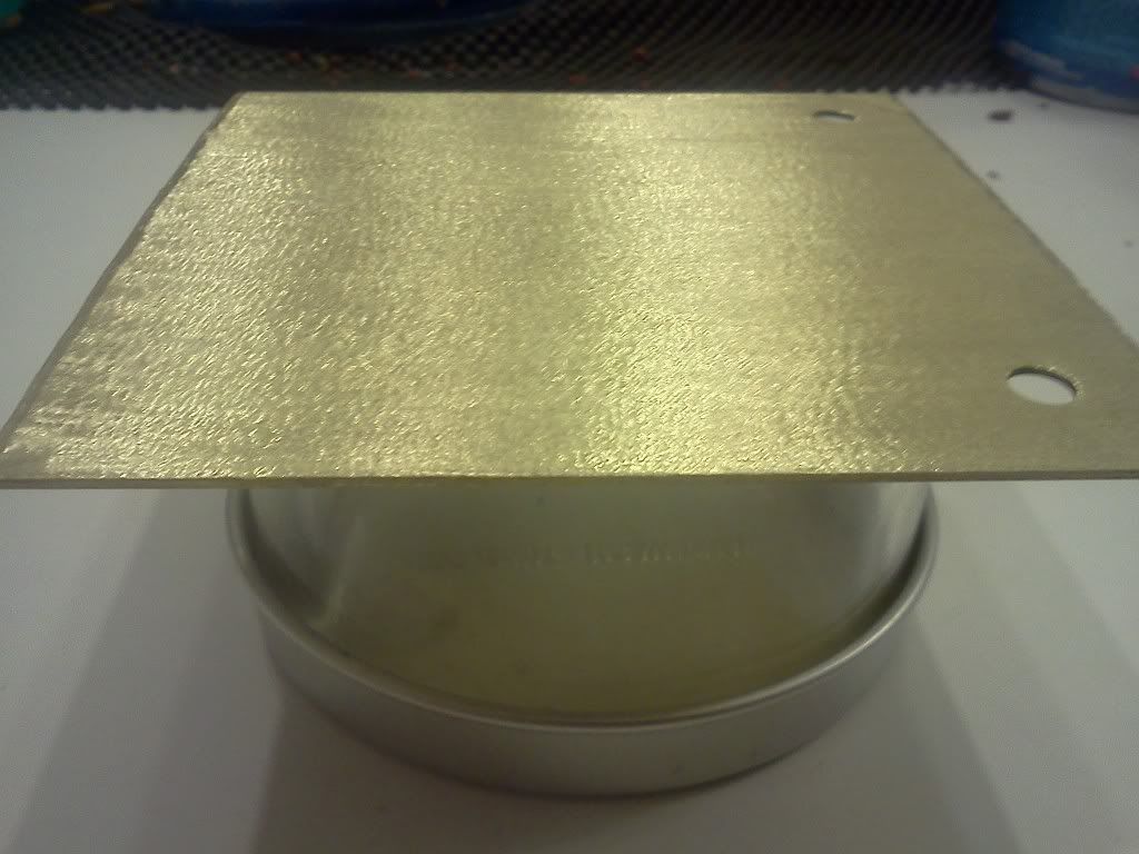
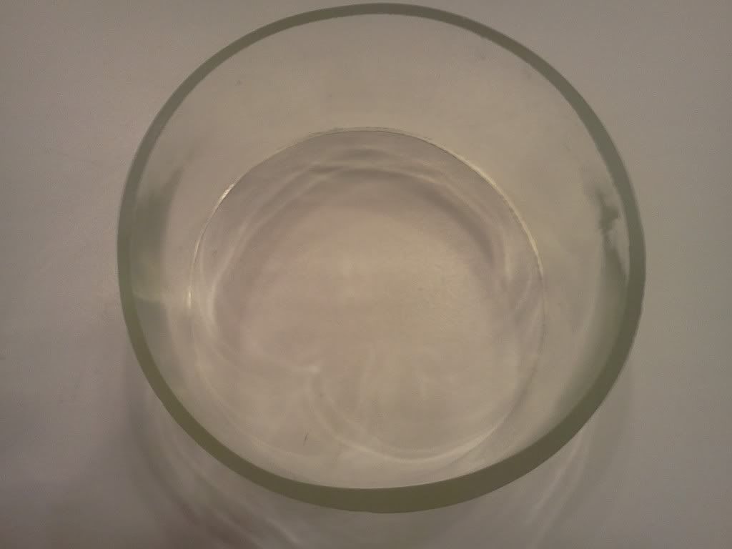
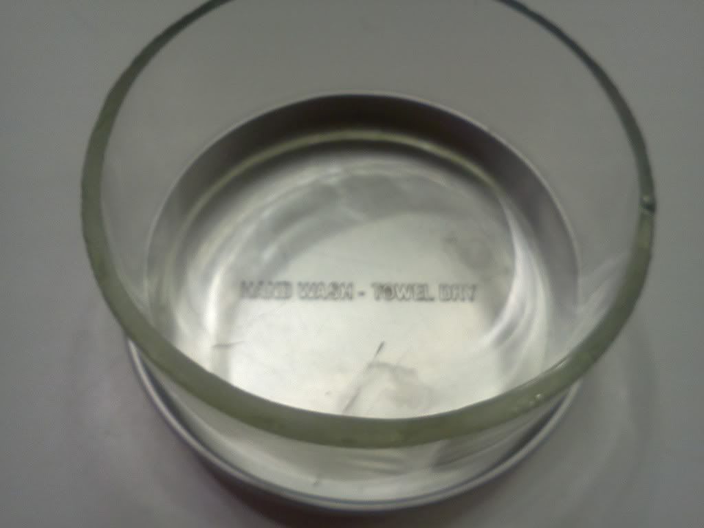
The pans are almost a perfect fit for the glass displacer cylinder I cut out of a bottle with an inner dia of appr 3 3/8". There's maybe 1mm play, mostly due to the bottle's non-uniform diameter. A bit of RTV and there should be no problems with air leakage. The pans seem strong enough for a LTD, pressing on the center when upside down gives no bend without substantial force, but this may be more to do with the form than the thickness.
Image
Image
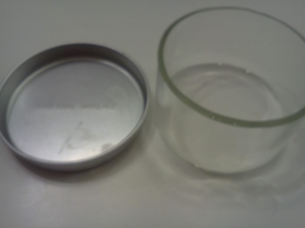
This will be set into a cutout of the stainless steel hot box, with an appropriate mating gasket to prevent the posibility of bi-metal corrosion.

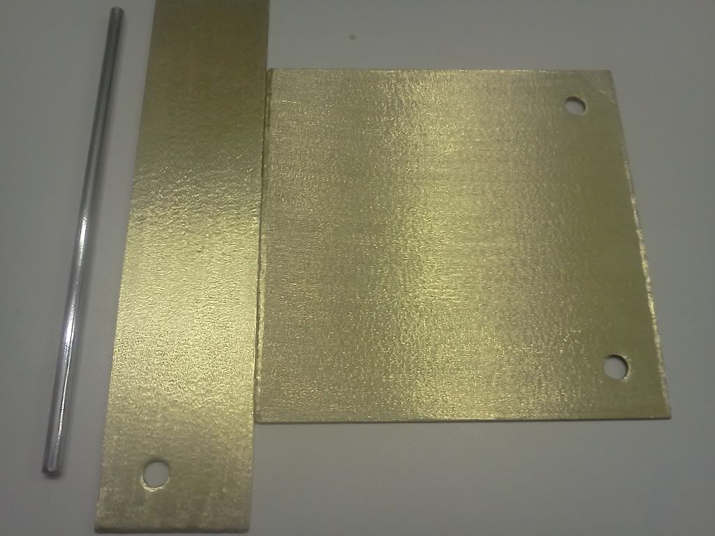
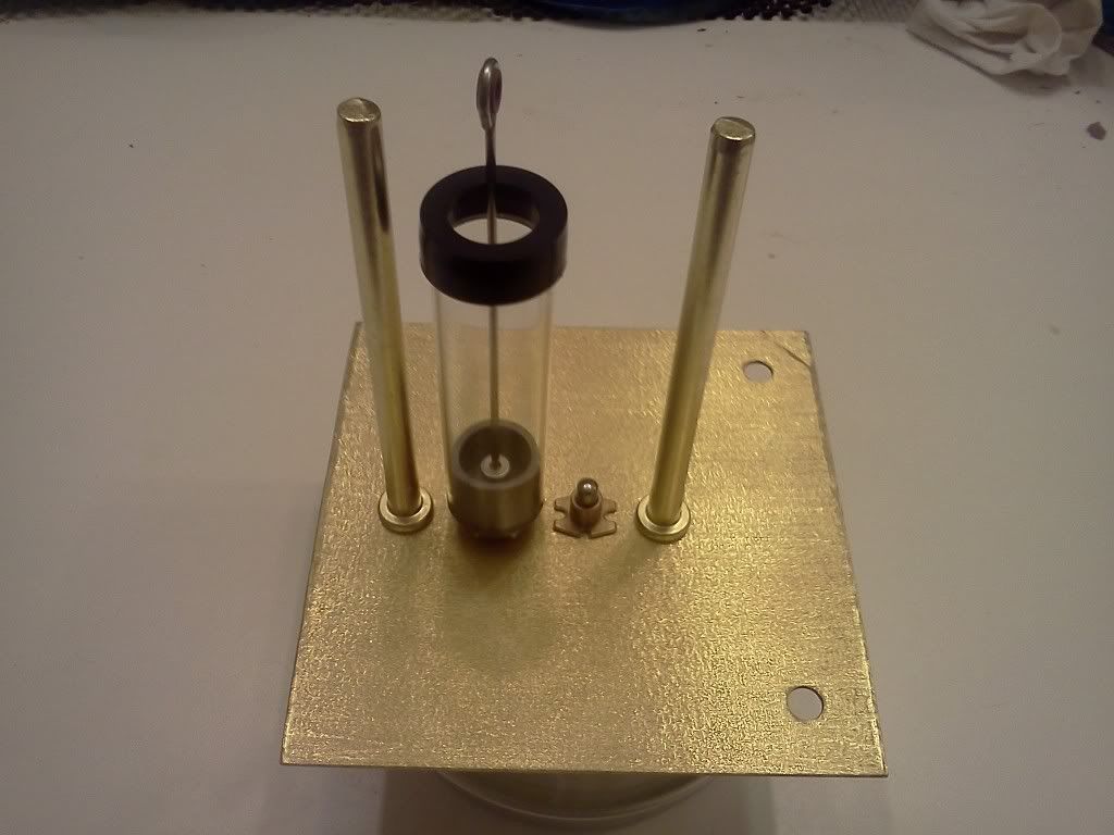
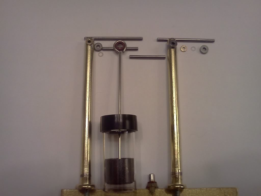
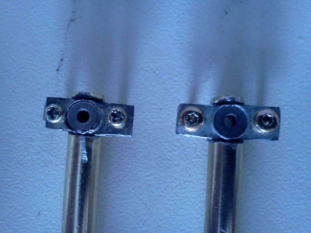
I cut the brass top plate today as well, decided to go square (might go octoganal) due to my lack of a lathe and lack of practice with a grinder for cutting. The existing holes are perfectly placed for the sign posts, so I measured to make use of them in my cutting. Don't know what the gauge of the brass sheet is, but it measures about 1/32", so it's not easy to work with hand tools, but I'm getting decent results. I'm actually kinda proud of my cut, seeing as how I did it free hand letting the cutting disc (grinder) work as the guide once my cut was started, then deburred with the dremel. Lots of cleanup and polishing to look forward to!
Image

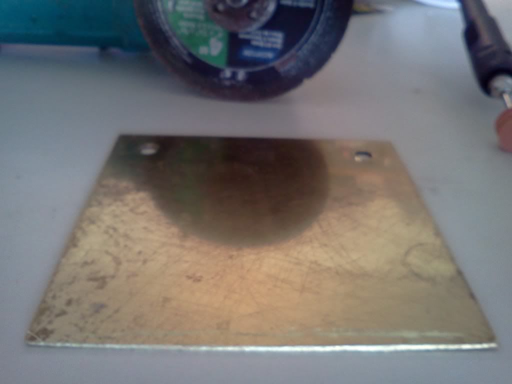
All of you with access to shop tools, I truly envy you right now. I spent 2 hours wet sanding the displacer tubes, and I've still got probably another 2 hours to go before I'll be happy with it (spreading the tedious jobs out over days helps keep me from getting frustrated). With a belt sander it would have taken me 5 minutes. While I'm happy with my brass sheet cut, it's not perfect, and you do see a bit of light when placed on a flat surface, but it looks good to the naked eye.
If I seem argumentative, I apologize. I like to explore many sides of an issue.
I love to be shown I'm wrong, after all, Dad always said to learn from my mistakes!
Jerry
Posts: 79
Joined: Sun Jul 29, 2012 10:42 pm
Location: Las Vegas

Re: LTD Power by Bagel

Post by Jerry »

Another part from recycled materials. Using an oil & vinegar caddy left over when we switched to a different style of caddy at the restaurant. Will be cutting the crankshaft from this, with the crank webs cut from the brass plate shown previously. The discoloration on the lower cross members is due to being dirty, no corrosion.
Image
Got some advice via email from Jan Ridders today, makes me more confident this engine will run and be capable of powering the LEDs!
If I seem argumentative, I apologize. I like to explore many sides of an issue.
I love to be shown I'm wrong, after all, Dad always said to learn from my mistakes!
Ian S C
Posts: 2218
Joined: Thu Dec 02, 2010 5:15 am
Location: New Zealand

Re: LTD Power by Bagel

Post by Ian S C »

Jan is a great help to all engine builders who ask his advice. My LTD uses two old frying pans, the small one
3 mm thick on the bottom, the larger one 5 mm thick on top, I cut a ring from around the big one, drilled six holes around the inside of the ring, made a hub with six matching holes, cut some bike spokes and glued them in the holes to make a flywheel (didn't have any Bagels), didn't have any clear plastic, or glass, so used a bit of plastic drain pipe. Ian S C
Jerry
Posts: 79
Joined: Sun Jul 29, 2012 10:42 pm
Location: Las Vegas

Re: LTD Power by Bagel

Post by Jerry »

Thanks Ian! I've been contemplating the flywheel, sounds like a good method to build one from scrap. I'm going to enclose it with one of the rings from those stackable plastic kids toys where there are several different sized rings they can stack on a central pole. I'll cut the appropriate sized plastic ring in half, place the flywheel inside it, then paint it to look like a bagel. Pics to come of course.

Jan's advice was very thorough, and included the following formula I thought might be helpful to others here:
R = (Vp + Vd) / Vp
  1. R is a value to be determined by the type of engine you are building and it's designed operating temp
    • High temp engine (Temp dif 300-400C): R = 1 or 2 (virtually identical pistons, primarily refers to alpha type engines)
    • LTD (coffee cup) (Temp dif 60-80C): R = ~50 (this boils down to a diameter ratio of ~7to1 assuming strokes are identical, 7~=sqrt50)
    • LTD (human hand) (Temp dif ~10C): R = as high as possible (~100, or ~10to1)
  2. Vp = Swept Volume of Power Piston
  3. Vd = Swept Volume of Displacer Piston
Last edited by Jerry on Sat Aug 11, 2012 6:28 pm, edited 1 time in total.
If I seem argumentative, I apologize. I like to explore many sides of an issue.
I love to be shown I'm wrong, after all, Dad always said to learn from my mistakes!
Ian S C
Posts: 2218
Joined: Thu Dec 02, 2010 5:15 am
Location: New Zealand

Re: LTD Power by Bagel

Post by Ian S C »

Jerry, thanks for the formula, could be handy, will be for the ones that are new to Stirling Engines. Two or three years ago I came across two charts, one for high temp, and the other for low temp engines. There was a diagram of both types and you could match up the dimentions, in relationship with the temperature, and pressurisation, from standard atmospheric, up to a few hundred psi. I went back the next night meaning to copy it, and do you think I could find it, well I'v looked of and on ever since, but i can't find it, Oh well never mind, or as we say in New Zealand, she'll be right. Ian S C
theropod2
Posts: 147
Joined: Tue Aug 16, 2011 5:05 am

Re: LTD Power by Bagel

Post by theropod2 »

Ian,

I found a PDF that may have been what you saw once upon a time.

Here's the LINK to what I found.

R
Jerry
Posts: 79
Joined: Sun Jul 29, 2012 10:42 pm
Location: Las Vegas

Re: LTD Power by Bagel

Post by Jerry »

If I posted Jan's entire email, it would mirror that PDF pretty well, small world!

Got a bit more work done today, not much, it's slow going since I'm learning to work all the materials as I go. While testing out various dremel bits on the brass finish, I found you can get an interesting finish with some of the stone bits. I like the results, and have decided to go with it on exposed surfaces. Similar to a brushed finish, I guess you could call it a stoned finish. Here's a couple of pics:

The brass top plate and sign board together with the main length of crankshaft (won't drill the rest of the holes till all parts are ready)
Image

The aluminum pan, glass displacer cylinder, and brass top plate stacked
Image

Next, attempting to bend a three sided box out of the stainless steel sheet. Hoping to finish this week, time permitting.
If I seem argumentative, I apologize. I like to explore many sides of an issue.
I love to be shown I'm wrong, after all, Dad always said to learn from my mistakes!
Ian S C
Posts: 2218
Joined: Thu Dec 02, 2010 5:15 am
Location: New Zealand

Re: LTD Power by Bagel

Post by Ian S C »

Jerry, i think you are proberbly right about using aluminium for the displacer end, rather than the stainless.
Regenerator on LTD motors: One I have seen an artical onhad a foam displacer, with three or four large holes through it, these were packed with steel wool, the displacer was made large enough in diameter to alow very little air to pass around it, rather to go through the steel wool. Ian S C
Jerry
Posts: 79
Joined: Sun Jul 29, 2012 10:42 pm
Location: Las Vegas

Re: LTD Power by Bagel

Post by Jerry »

Thanks Ian. I do think I'll use holes filled with steel wool in the displacer, but I can't make the displacer a very tight fit due to the non-uniform bore of the cylinder. Machine cast glass bottles have tons of humps and hollows, so tightest fit I can achieve is about 1.5mm without risk of catching a hump. I'm going to be starting with floral foam since it's so simple to shape by hand, I've used it in my soda can models wrapped in aluminum from either another can or foil. The way I look at it, the worst case scenario is I waste a bit of time making holes and packing with steel wool. Even if most of the air goes around the displacer, the steel wool is so light it can't hurt, and will definitely give some regeneration effect I'm sure.
If I seem argumentative, I apologize. I like to explore many sides of an issue.
I love to be shown I'm wrong, after all, Dad always said to learn from my mistakes!
Ian S C
Posts: 2218
Joined: Thu Dec 02, 2010 5:15 am
Location: New Zealand

Re: LTD Power by Bagel

Post by Ian S C »

Sorry Jerry, should have been clearer, I ment to say that there should be enough clearance for there to be no chance of the displacer contacting the walls of the cylinder, but you'v got it anyway. Ian S C
Jerry
Posts: 79
Joined: Sun Jul 29, 2012 10:42 pm
Location: Las Vegas

Re: LTD Power by Bagel

Post by Jerry »

Got very little work done today, but did manage to scrounge up the crank stands and sign posts, as well as finish the ends of the displacer cylinder. Was looking through a box of old parts for some bushings for a project for my niece, came across an unopened pack of 3 3/4" brass gate hinge pins that should work perfectly. I'll tap the heads and use counter-sunk screws under the brass top plate with o-rings for a nice air-tight fit.

Here's another shot of the parts coming together. I'm showing a small bearing in place of the displacer seal for this shot, and I'll have to cut the airpot about in half, but it's all fitting togther nice:
Image

Here's the finished edge to the displacer cylinder, found that the sandpaper was getting worn down fast, switching sheets more often made it go much quicker. Notice how non-uniform the inner radius is, gonna have to pay close attention to the displacer's shape/fit:
Image
If I seem argumentative, I apologize. I like to explore many sides of an issue.
I love to be shown I'm wrong, after all, Dad always said to learn from my mistakes!
Jerry
Posts: 79
Joined: Sun Jul 29, 2012 10:42 pm
Location: Las Vegas

Re: LTD Power by Bagel

Post by Jerry »

Had to do a design change, point bearings won't work with the bagel flywheel on the the outside of the crankstands, the crankshaft has to go through one crankstand. This means I have to use a smaller crankshaft than planned as well, since I don't want to build bearing boxes on top of them. So the newly designed crankshaft is built from 4 old 1.5v motors used in a brushbot I made a year or so ago. The steel cranks will be cut to fit, and the bearings are 3 piece with a brass bushing, teflon or nylon washer, and steel bearing, will use the fourth bearing for the displacer on the crankshaft.

Got to work on it right away. After cutting the airpot actuator with the dremel and cleaning it up with sandpaper, I drilled and tapped the bottom of the crankstands (2 hours and three bits with a dremel, hinge pins are tough, and had to let it cool often). I then drilled through one crankstand, and a little more than half way through the other. I then bored out the front of each hole to fit the brass bushing, which will be epoxied on along with the steel bearing for good lateral support. I will have to mount a stop on the terminating side of the crankshaft, and install it when I epoxy that crankstand's bearing on, since I've no way to tap the bushing in. Here's another pre-assembly mock up pic:
Image
If I seem argumentative, I apologize. I like to explore many sides of an issue.
I love to be shown I'm wrong, after all, Dad always said to learn from my mistakes!
Jerry
Posts: 79
Joined: Sun Jul 29, 2012 10:42 pm
Location: Las Vegas

Re: LTD Power by Bagel

Post by Jerry »

Spent what time I could this weekend working on the bearings. I've ground the two crankstands down to provide as flat a surface as possible for the mounting. As I've mentioned previously, I am using a dremel for most of the work. I used a table that has a removable section, and opened it enought to lay the dremel in. By adjusting the opening in the table, I can adjust the dremel cut-off disc's height. I then clamped one of the hinge pins to a board, and run the board back and forth across the table, grinding a decently flat surface to mount on. However, it is not perfect, once I hand mount the bearings and a crankshaft piece, you can see a slight tilt. I'm concerned with slapping on epoxy to hold the bearings in place, it is too easy to get messy and end up partially plugging either the bearings or the hole drilled through one of the crankstands.

So, I decided I need a bearing flange of some sort. I was measuring the opening in the motors these bearings and crankshaft pieces were salvaged from, and realized I could cut the flange out of them. These are toothbrush vibrator motors, about 1"x3/4"x5/8". I should have some time over the next couple of days to cut them out and drill four set screw holes. I'm hoping by using four set screws, with a bit of foam in between the two flanges, I should be able to tweak the alignment nearly perfect. A touch of epoxy once it's aligned, and I think this will work. Here's a computer model of what I'm attempting:
Image

Gotta stop by some local workshops and see if I can scrounge up a chip of UHMW for the displacer gland. Was going to use graphite, but this is more inline with the concept of using recycled parts. Getting anxious to put this baby together!
If I seem argumentative, I apologize. I like to explore many sides of an issue.
I love to be shown I'm wrong, after all, Dad always said to learn from my mistakes!
Jerry
Posts: 79
Joined: Sun Jul 29, 2012 10:42 pm
Location: Las Vegas

Re: LTD Power by Bagel

Post by Jerry »

Got the crankstands done today. Didn't have a bit small enough to make 2 holes on each side of the flanges, but one on each side seems to do fine. I cut the flanges out of the engine bodies, pressed the bearings back in on a board with a flat punch. I then mounted them and adjusted each srew till I had a tight fit with as little friction as possible. I then put the crankshaft into the dremel, threaded it through the attached bearings, and turned on the dremel to use the crankshaft itself as a boring tool of sorts. With a bit of liquid wrench the crank spins nice and free, and is aligned with the other crankstand. Not as pretty as a machine shop, but I'm not too disappointed for freehand with a dremel, even though I did scrape up the one flange pretty good. A little loctite/resin once everything is assembled and it should be strong enough to support the flywheel, since I can spin the front crankstand around the crankshaft violently without any wiggling. The crankstand on the left is the rear one and is not drilled through, the one on the right is the front one and is drilled through with a flange on each side.
ImageImage
ImageImage

Next, cutting the crankwebs and assembling the crankshaft.
If I seem argumentative, I apologize. I like to explore many sides of an issue.
I love to be shown I'm wrong, after all, Dad always said to learn from my mistakes!
Ian S C
Posts: 2218
Joined: Thu Dec 02, 2010 5:15 am
Location: New Zealand

Re: LTD Power by Bagel

Post by Ian S C »

Jerry, sound like your making progress, good on you. Ian S C
Post Reply