Displacer - Crankshaft connecting rod?
Displacer - Crankshaft connecting rod?
Hi, as you will have gathered by previous posts, i am a complete beginner at building tin can Stirling engines. My basic question today is what ideas for a connecting rod between the displacer and crankshaft? I have tried various things , but cannot get a good mechanism working that has a smooth action. The dispacer has a pin which is bent at a 90 degree angle and am trying to figure out the optimum way of connecting it to the crankshaft. Any ideas?
Re: Displacer - Crankshaft connecting rod?
I use a 1mm wire zig zag with hoops on either end. it works very well
- DSC02799.jpeg (43.71 KiB) Viewed 5834 times
http://www.scraptopower.co.uk My web site, Stirling engines and AE stuff.
Re: Displacer - Crankshaft connecting rod?
I use a very similar method, but my bend is less radical.
Jim Larsen
http://StirlingBuilder.com
http://StirlingBuilder.com
Re: Displacer - Crankshaft connecting rod?
Jim, what do you seal the rod for the displacer with (as it comes out of the can), do you glue the wire were its twisted together (I'd proberbly solder it). How many units on that rig ie power/ displacers? Ian S C
Re: Displacer - Crankshaft connecting rod?
Ian,
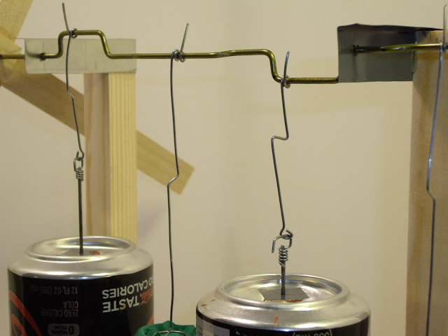
My engines are intentionally low-tech. I am creating several designs for engines that are intended for students and first time builders. So I try to focus on parts that are easy for most people to find, and designs that can be built with very few tools.
The gland for the displacer pushrod is passing through a piece of tin that I cut from the side of a paint can. The pushrod is made from music wire. It is a high carbon steel that is very stiff and hard. I drilled a hole in the tin slightly smaller than the pushrod, then forced the pushrod in for a perfect fit. The tin is sitting on top of an old rusty hex nut.
The hook on the end of the pushrod is attached with super glue. For this application, it works very well. The music wire is hard to bend, so this is a good alternative.
This picture is of my recent two cylinder engine. There are two pressure chambers and two drive cylinders. The most challenging part of this design is that long crankshaft. That was made from a wire coat hanger.
Here is a video of this engine in motion: http://www.youtube.com/16strings
Jim Larsen
http://StirlingBuilder.com
http://StirlingBuilder.com